Non-Submersible Units
The DTU-A is a non-submersible analog converter for your ANB Sensor. We recommend using anb_utils as an easy way to communicate with your sensor.
Set-up:
- Simply connect the sensor to the DTU_A and the USB to the computer.
- Connect the DTU-A to the data logger using the wiring instructions below.
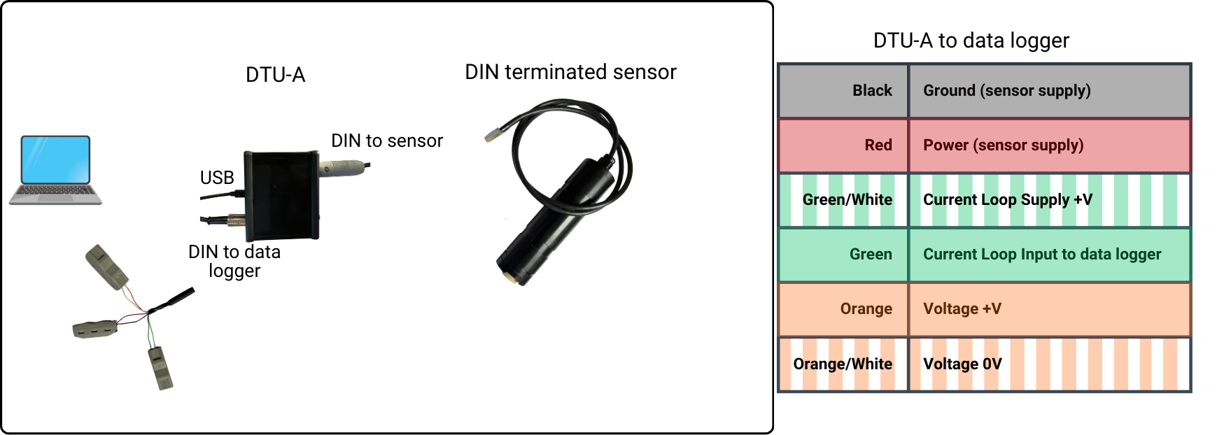
If loop current is used, make sure to connect the green wires to the loop current power source using a suitable load resistor i.e. 250 Ohms
- Press the power on switch on the DTU-A and the light will come on to show the DTU-A has power.
- Wait for the sensor to beep twice.
- You can now communicate to the sensor via anb_utils.
The loop current should be supplied with a voltage between 12 - 24V.
The data logger doesn't need to be connected for communication with the sensor through anb_utils.
Viewing the DTU-A Information Screen
Select 3. Command Line Prompt from anb_utils Main Menu, or open a terminal connection. Type:
#800
The DTU-A splash screen will be displayed:
ANB SENSORS DTU - A

Firmware Version : DTUA_4.3
DTU-A Serial Number : 123456

pH Range:
     2 - 10 pH

Current Output:
     4 - 20 mAmps = Proportional to pH value

Voltage Output:
     0 - 5.0 Volts = Proportional to pH value
This screen confirms:
- firmware version
- DTU-A serial number
- configured pH range
- current output scaling
- voltage output scaling
Using TEST MODE
TEST MODE allows the analog outputs to be stepped through fixed output values so that the connected analog input system can be verified.
In 3. Command Line Prompt from anb_utils, or in a terminal connection, type the following command:
TEST
The DTU-A will enter TEST MODE:
TEST MODE
0% output
Press [ENTER] to step, X to exit
Press [ENTER] to step through each output level.
The DTU-A will sequentially output:
25% output (8.00mA / 1.25V)

50% output (12.00mA / 2.50V)

75% output (16.00mA / 3.75V)

100% output (20.00mA / 5.00V)
At each stage:
- verify the measured value on the connected analog input device
- confirm that the displayed current or voltage matches the expected value
Example:
At 25% output, the receiving system should read:
- 8.00 mA, or
- 1.25 V
Once all output levels have been checked, the DTU-A will display:
TEST END
Press X at any time to exit TEST MODE.
To start scanning:
- Either send a
startcommand from anb_utils' command line prompt.
or - Set Autonomous Operation, configure the start delay and measurement interval parameters and the sensor will start according to the programmed timing sequence on power up.
- Wait for first measurement output (until the sensor provides a measurement there is no change on the output).
We recommend a splice kit when connecting the DTU-A to a pigtailed sensor.
Further details of the wiring:
| 6 Pin DIN | Colour | Connect to | Notes | Current Sensing Equipment | Description |
|---|---|---|---|---|---|
| 1 | Green/White | Loop Current Supply +V | 4-20mA Loop Input 24V Max | ||
| 2 | Orange | DVM +V | 0V to 5V output | ||
| 3 | Black | Sensor Supply 0V | Sensor Power 0V | ||
| 4 | Green | Current sensing equipment input | Through a 250 ohm resistor if required | Connect Current Output to -Loop Current 0V (dual supply) -Sensor Supply 0V (single supply) | 4-20 mA Loop Output |
| 5 | Red | Sensor Supply +V | Sensor Power 24V Max | ||
| 6 | Orange/White | DVM 0V | 5V Ground Reference |
If you require further support please contact support@anbsensors.com