Flow Cell
Please watch this short video for a summary of how to use the Flow Cell.
If you have other questions please contact us at support@anbsensors.com.
Flow Cell Contents
- 1x Flow Block
- 1x Securing Cup (Usable with all AQ and OC models)
- 1x Hand Twist Jubilee Clip
- 2x Pre-Installed BSPP – ½” Barbed hose
- 2x O-Rings - (only one is required)
note
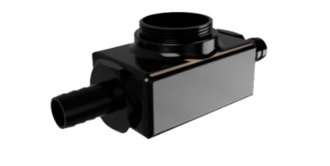
The Flow Block is fitted with BSPP ½” barbed hose adaptors. If required, the adaptors can be removed and replaced using a 30 mm spanner.
Installing your Sensor into the Flow Cell
1. Installing the O-Ring
Install the O-Ring in the groove at the Transducer end of the Sensor.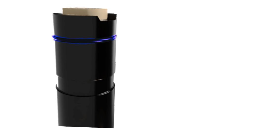
caution
Ensure that the O-Ring is greased, displaying a noticeable shine without any visible clumps of grease.
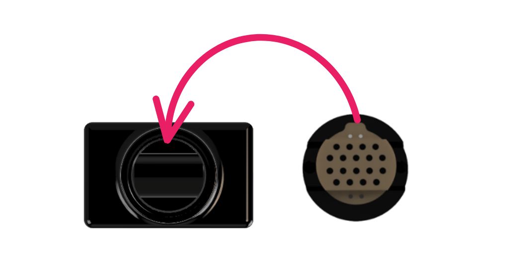
2. Installing the Sensor into the Flow Block
- Align the raised platforms in the Flow Block with the recessed areas of the Transducer.
- Ensure that all straight lines are parallel and press the Sensor down into the Flow Block.
tip
You will hear a distinct click sound once the O-Ring is correctly engaged.
3. Securing the Sensor with the Securing Cup
- Make sure that the top of the thread on the Flow Block aligns precisely with the edge groove on the sensor. If it appears raised, it indicates incorrect engagement.
- After aligning the top of the thread and the edge groove, proceed to screw on the Securing Cup until you feel resistance.
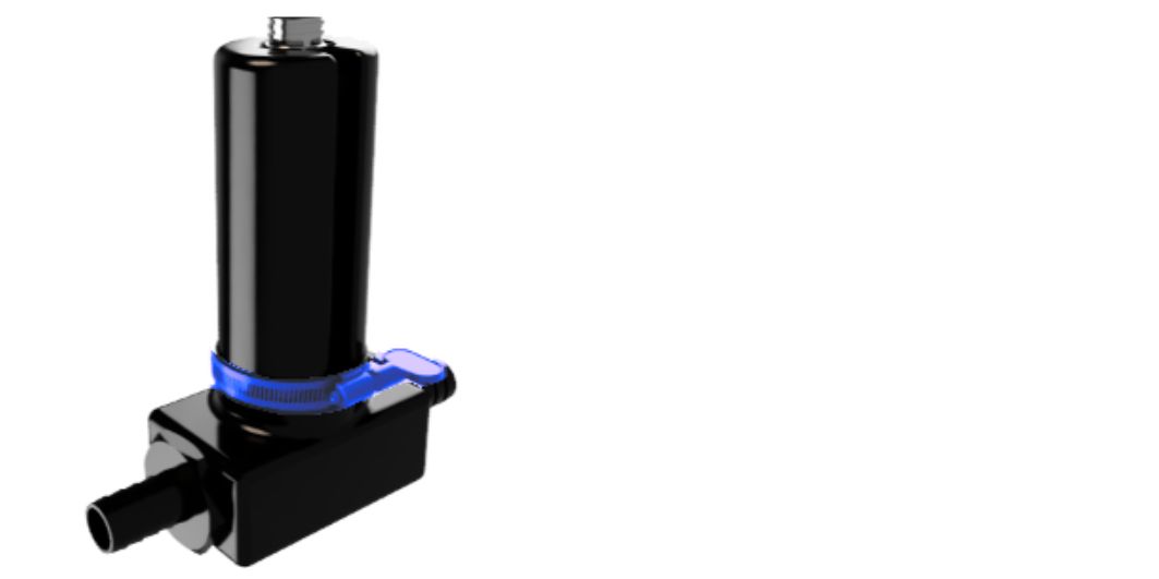
- Slide the Jubilee Clip over the threaded part of the Securing Cup located at the bottom and tighten manually until you feel resistance. At this stage, the jubilee clip should stay in position without any mobility unless deliberately loosened.
4. Operation
- Use the flow cell in an upside-down orientation, ensuring the sensor transducer is pointing downwards, to prevent air bubbles.
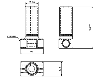
Dimensions
For further support please contact support@anbsensors.com