Connecting & Powering up
Overview
There are three methods to power and communicate with your sensor:
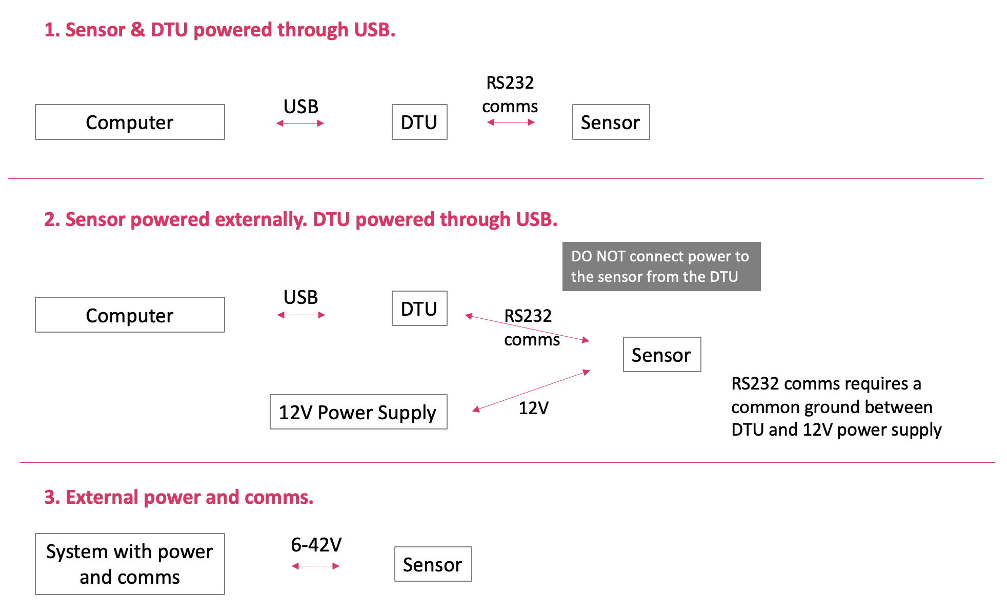
Connecting
Pigtail cabled sensors
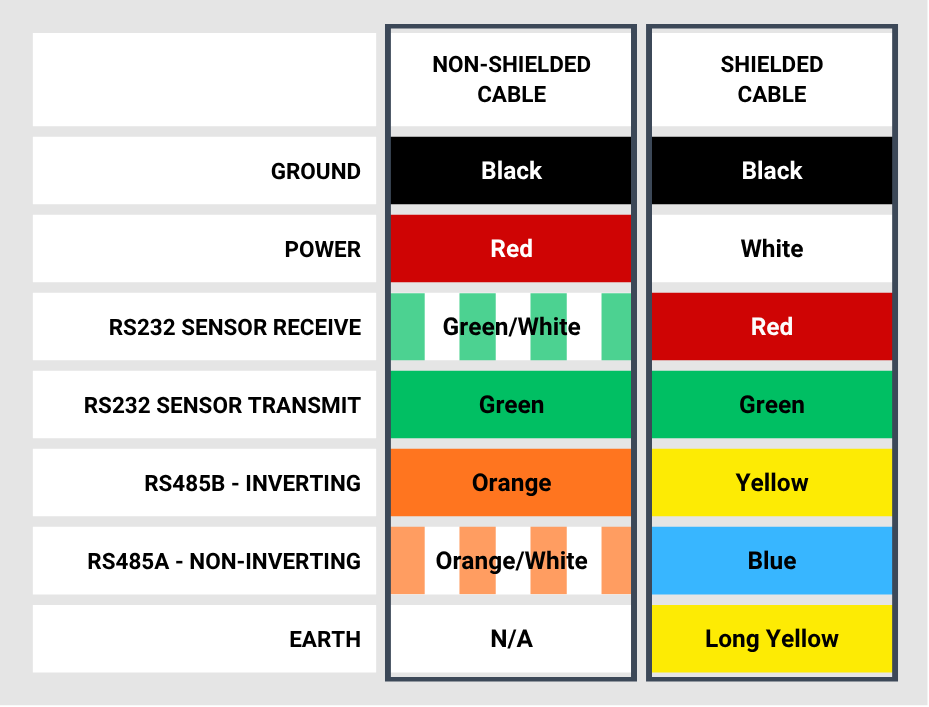
Sensors fitted with a 6-core pigtailed cable should be connected as shown in the diagram below. Two cable types are available, so select the diagram that corresponds to your cable.
Sensors of an earlier revision, identifiable by a blue wire, should be connected using this alternative diagram.
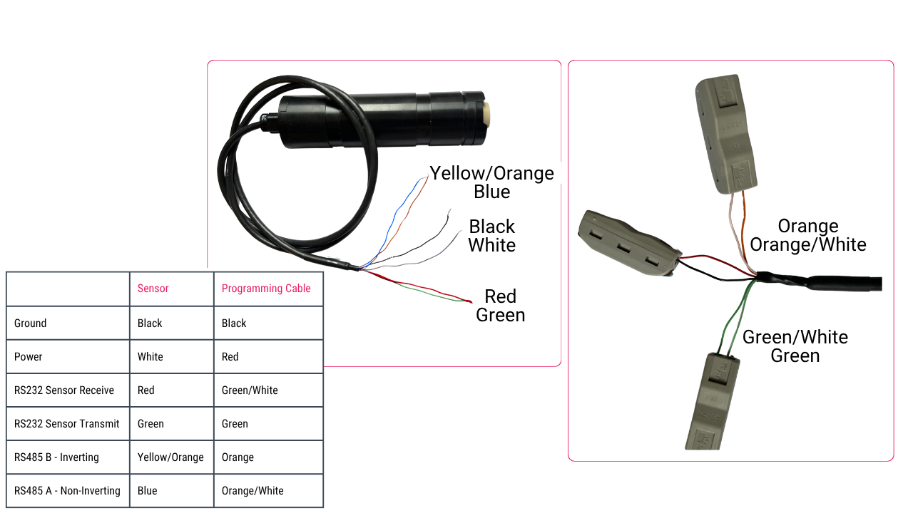
Because of the potential for different vendors to use different signal definitions, if you connect our sensors' A/B wiring to your communication device and communication does not work, try reversing the signals
SubConn cabled sensors
For sensors terminated using a MCBH6M connector, follow the pin-out below:
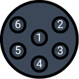
| Pin | Function |
|---|---|
| 1 | Ground |
| 2 | Power |
| 3 | RS232 Sensor Receive |
| 4 | RS232 Sensor Transmit |
| 5 | RS485 B - Inverting (for sensors with a serial number > 3000028) |
| 6 | RS485 A - Non-Inverting (for sensors with a serial number > 3000028) |
Because of the potential for different vendors to use different signal definitions, if you connect our sensors' A/B wiring to your communication device and communication does not work, try reversing the signals
Powering
The sensor can be simply powered by any power source (6-42V) or via the DTU from a USB port of a computer.
Via battery
- Connect the sensor to power
- Wait for the sensor to beep twice
Via the DTU
- Connect the sensor to the DTU and the USB to the computer
- Press the power on switch on the DTU and the light will come on to show the DTU has power
- Wait for the sensor to beep twice