ONLY FOR USE IN OCEAN WATER
If tested in dry or fresh water conditions for comms validation, the sensor will not suffer damage, however, no pH values will be displayed
ENSURE SENSOR IS FULLY IMMERSED IN OCEAN WATER WHEN IN DEPLOYMENT
Hardware Setup
Communicating with your sensor
Deploying your sensor
Understanding your sensor display
Autonomous mode instructions
Hardware Setup
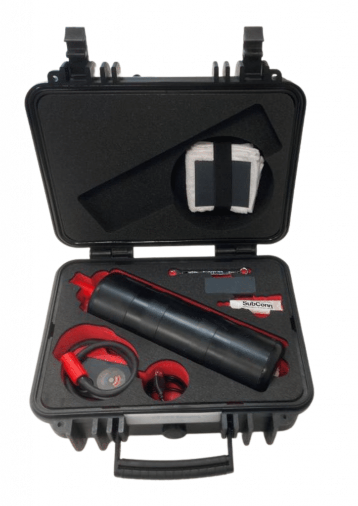
- Main Sensor Housing with Transducer Installed
- Subcon Protector Cap
- Data Retrieval Unit
- Male to Female SubConn Connector
- ANB Microfiber Towel
- 8mm Spanner
- Abrasion Block
- ANB Approved Silicone Grease
- Transducer
- M5 Titanium Bolt x3
- M5 Titanium Nut x3
- M2 Bolt x3
- O-Ring x2
- ANB Sensor Plate
Connecting the sensor to your control system
The sensor terminates with either a 4 pin or 6 pin SubConn connector.
The 4 pin uses a MCBH4M connector with the following pin-out:
| Pin | Function | If sensor delivered after 01/01/22 or if self-installed power board |
| 1 | Power | 10-20 V @ approx 180 mA |
| 2 | RS232 Sensor Receive / RS485 B | RS485 A |
| 3 | RS232 Sensor Transmit / RS485 A | RS485 B |
| 4 | Ground |
The 6 pin uses a MCBH6M connector with the following pin-out:
| Pin | Function | If sensor delivered after 01/01/22 or if self-installed power board |
| 1 | Ground | |
| 2 | Power | 10-20 V @ approx 180 mA |
| 3 | RS232 Sensor Receive / RS485 B | RS485 A |
| 4 | RS232 Sensor Transmit / RS485 A | RS485 B |
| 5 | No Connection | |
| 6 | No Connection |
Communicating with your sensor
Your sensor will arrive with a RS232 interface and in an user-controlled, continuous measurement mode
Set-up
Using a terminal program
- Launch Terminal Program (e.g. Tera Term)
- On Set-up menu select serial port from the drop down. In the resulting window select the correct com port
- Select speed = 115200, Data = 8bit, Parity = none, Stop bits = 1, flow control = none
- On Set-up menu select terminal
- New line options in resulting window should be Receive = auto and Transmit = CR, click OK
- Connect sensor to power and control system
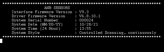
Once Set-up is complete, turn on the sensor and then will wait for commands to be entered. The sensor will beep once when turned on. It will not perform any function until it is instructed to do so
The following will be displayed:
The sensor will accept commands typed in either upper or lower case. Backspace can be used to correct typos. All commands must be followed by the ENTER key.
If you are using a parsing script on a connected microprocessor to access the menu functions and change the parameters in the sensor you will need to write a script that issues commands mimicking accessing the menu.
In this guide commands will be shown in PINK.
The Primary Menu
MENU – displays the main functions of the sensor as shown below:
System Functions
VERSION – Display the sensor firmware revisions, Ser No. and clock
TIME – Change the date and/or time in the sensor clock
MODE – Change the sensor from controlled to autonomous mode
CONFIG – Change the communications interface format (RS232/RS485)
Measurement Functions
INTERVAL – Changes the time delay between successive measurements blocks
SCAN – Commence scanning and recording data
SLEEP – Place sensor into low power mode, wake up on terminal keystroke
SHUTDOWN – Save any current result and stops scanning
Data Functions
LIST – List all result files with the date of file creation
RESULTS – Select result file(s) for download (performs ‘LIST’ first)
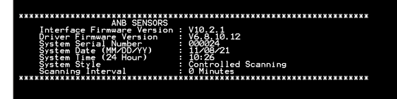
VERSION
This utility displays the system firmware revisions, the system serial number and the current date and time of the internal clock calendar. The display looks like this:
Should you be in discussions with ANB Sensors regarding the operation of your device, you may be asked to refer to this command.
TIME
This utility command allows for the internal clock and/or calendar to be altered. After typing this command, the following is displayed.
The current time and date is set to;
07/24/21 08:34
Enter date in this format;
MM/DD/YYYY [ENTER]
To accept current date Press [ENTER]
Here you can either enter a new date, in the format specified, or simply press ENTER to accept the current date.
On pressing ENTER the current time setting is displayed.
Enter time in this (24 hour) format;
HH:MM [ENTER]
To accept current time Press ENTER
You can either enter a new time in the specified format, or simply accept the current time by pressing ENTER.
On pressing ENTER the new date and time is displayed, and the system will reset. (If the new date is different from the current results file, a new file will be opened).
MODE
This function allows the user to choose between modes of operation of the sensor. The menu will be displayed as shown below:
Please enter a Style number.
It MUST be 1 digit and only be the digits 1 – 2
1 115200 baud, Controlled Monitoring
2 115200 baud, Autonomous Monitoring
After selecting your style the system will reboot and show the splash screen with the newly selected mode
More details on the Autonomous Monitoring mode can be found here
CONFIG
This command allows you to swap between RS232 and RS485 communication protocols.
Upon typing the command, the following options are available.
—–WARNING—–
Using these commands will render your system inoperable if you do not have the selected interface equipment
RS232 – Change interface to RS232 standard
RS485 – Change interface to RS485 standard
Upon selecting either option, by typing RS232 or RS485 the following is displayed.
~~~~~~~~~~~~~~~~~~~~~~~~~~~~~~~~~~~~~~~~~~~~~~~~~~~~~
SENSOR MUST BE POWERED DOWN FOR THIS TO TAKE EFFECT
~~~~~~~~~~~~~~~~~~~~~~~~~~~~~~~~~~~~~~~~~~~~~~~~~~~~~
Whichever option is selected, the system will remain in the current state until the unit is powered down and then back up again, where it will now be in the communications protocol selected in the previous step.
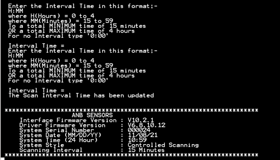
INTERVAL
This function allows you to chose the time between measurement blocks with a minimum of 15 minutes (0:15) and a maximum of 4 hours (4:00). Should you require continuous measurements, simply type 0:00.
The following screen showing your scan interval will be displayed.
SCAN
This function will tell the sensor to start scanning. The sensor will then provide the output as shown here
SLEEP
This function places the sensor into the low power mode. The following text will be displayed after selecting this function:
The Sensor will now enter Sleep Mode.
This is a low power mode, during which there will be no scanning function.
To leave low power sleep mode, just hit any key twice on the terminal keyboard. The Sensor will reset and be ready for commands.
SHUTDOWN
This function will tell the sensor to stop scanning, enabling the menu options to be accessed.
LIST
This command will list all the text files that contain scan results.
In continuous mode:
if sensor is kept on, only one file is created
if sensor is switched off/on in the same day, only one file is created
if sensor is switched off/on on different days, a new file is created
In delayed mode:
a new file is created each day
The listing looks like this:
ANBPH001.CSV N 07/23/21
ANBPH002.CSV N 07/24/21
Here you can see that the storage system contains two files, one created on 23rd July and one created on 24th July.
The file names are numbered consecutively, the file type (.csv) indicates that the file can be opened by either a text program or a spreadsheet program as a comma delimited file.
The ‘N’ after the file name indicates that the file has not yet been downloaded. This is explained fully in the RESULTS command.
RESULTS
This command allows the internally stored results file to be downloaded via the control communications into a terminal program (such as Tera term) where is can be saved to a text file on the host (controlling) system.
To use this command the procedure is as follows:
Type RESULTS and the following will be displayed (your available results files will be different)
ANBPH001.CSV N 07/23/21
ANBPH002.CSV N 07/24/21
***************************pH FILE DOWNLOAD**********************
Enter one of the following:
ENTER = All files (not previously downloaded)
nnn (3 digits 0 – 9) ENTER = That file (even if previously downloaded)
The results files are listed here.
Those marked with an ‘N’ are data files that have not been previously downloaded.
Those marked with an ‘S’ are data files that have been previously downloaded.
Open a receiving text file in your terminal program.
Once the terminal program is ready to receive the results file, either press the ENTER key to download any new files or select a specific file for download.
The download procedure can take some time, depending on the size of the file. Once the download is complete the following will have been displayed/downloaded.
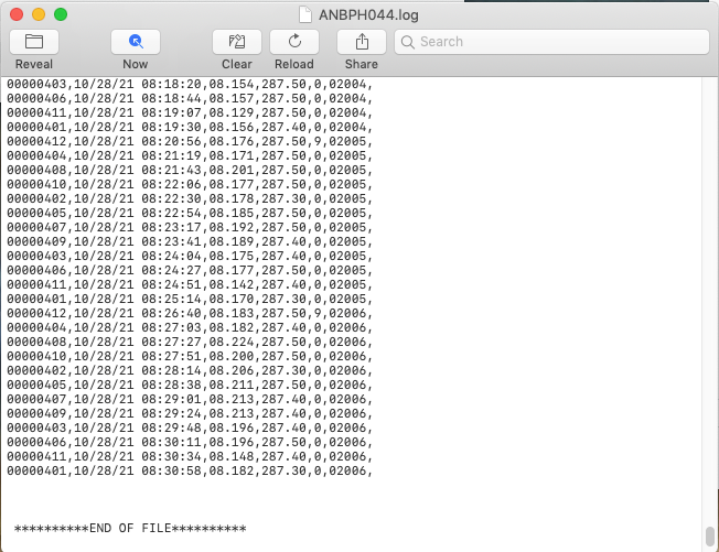
The first line of the generated text file will contain the file number from which the data was copied. Then the results data of the selected file will be listed. Finally, there is text that indicates that the download is complete. It is at this point that the receiving text file should be closed using the command on the terminal program.
If more that one file has been selected for download, all the files will be contained in this one receiving text file.
<ELECTRODE>,<TIMESTAMP>,<PH>,<TEMP>,<HEALTH><FILE NUMBER>
| Parameter | Description | Format |
| <ELECTRODE> | Electrode Number | Unsigned integer |
| <TIMESTAMP> | Sample timestamp | year:month:day hour:minute:second |
| <PH> | Sample pH value (pH) | Float (3 decimal places) |
| <TEMP> | Sample temperature (K) | Float (2 decimal places) |
| <HEALTH> | Sensor health status code (0 to 9, where 0=good, 9=sensor failed) | Unsigned integer |
| <FILE NUMBER> | File Number | Unsigned integer |
Deploying your sensor
- Use the Abrasion Block to abrade the surface of the installed transducer as shown here.
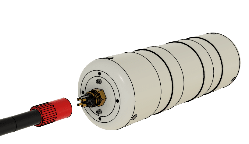
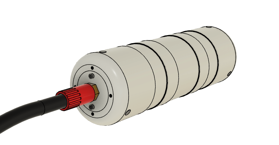
- Connect SubConn connector to sensor. See here for SubConn handling instructions.
- Switch on power to sensor, once connected the sensor will beep to confirm power supply.
- Set measurement parameters as detailed above
- The sensor will measure in the user defined mode.
- Once removed from the water, disconnect the sensor and dry completely.
- Reattach the SubConn protector to avoid any damage to pins.
Understanding your sensor display
$ANB,<CRC>,<STATUS>,<TIMESTAMP>,<PH>,<ELECTODE>,<TEMP>,<HEALTH><CR><LF>
| Parameter | Description | Format |
| <CRC> | Checksum | 4 digit hex number |
| <STATUS> | 0 | |
| <TIMESTAMP> | Sample timestamp | year:month:day hour:minute:second |
| <PH> | Sample pH value (pH) | Float (3 decimal places) |
| <ELECTODE> | Electrode number | Unsigned integer |
| <TEMP> | Sample temperature (K) | Float (3 decimal places) |
| <HEALTH> | Sensor health status code (0 to 9, where 0=good, 9-sensor failed) | Unsigned integer |
Displayed pH value
The number displayed for a pH reading can contain 3 types of data:
nn.nnn
The first is of course a real decimal number, that represents the pH value of the solution being measured, it is made up of 5 digits, 3 of which are after the decimal point.
– – . – – –
The second is 5 hyphens, all displayed pH results will contain this data. This signifies that the reference electrode does not give a valid response, therefore all pH calculations will be invalid. This can happen if the sensor is not immersed, if there is no transducer on the sensor, or if the reference element has failed during deployment.
If this is shown on the screen or in the pH file data, please contact ANB Sensors.
$$.$$$
The third is 5 $, which signifies that the system has not been able to determine a valid pH response yet. This could be due to a number of reasons, the most common of which is the health number.
Health Number
If you are using Firmware version Driver v7.0 and Interface v11.03 or v12.1
The health number represents the quality of data obtained from each individual sensor. The number ranges from 0 which is a healthy sensor, to 9 which is a sensor that will no longer be scanned.
A sensor with a health of 0 is scanned and its data is used in the monitoring of the pH of the solution and the quality and accuracy of other sensors in the array.
As a sensor starts to give a less accurate response, its health number is increased. It is a feature of this technology that a scanned sensor can improve its response as a consequence of being scanned, therefore as a sensor improves its response the health number can also be decreased, back towards zero and become a healthy sensor again.
Individual sensors with a health number from 1 to 8 continue to be scanned but the result calculated from the gathered data is not used in any cumulative data analysis. But rather if possible, to return a sensor to a working usable state.
Individual sensors whose health number reaches 9 are removed from the scan schedule and will no longer be used. They are deemed unrecoverable. They may be improved when the array is polished by hand.
If all the individual sensors scanned so far have a health number greater than 0, then the sensor cannot accurately determine the pH value. It will therefore display $$.$$$ as the pH number until it can scan a healthy individual sensor and use that data to calculate the pH.
If you are using Firmware version Driver v11.0 and Interface v15.0
The health colour represents the quality of data obtained from each individual sensor. Through a terminal program, the colour can be Green which means the transducer is healthy, Amber which means the transducer is ok, Red which means the transducer requires abrasion and Magenta which means the transducer needs replacing.
If integrating using your own interface/logging system, the text at the end of each line is to generate a coloured square on the monitor and operates as follows:
0x20 which is a space character to get a gap between the square and the last text character.
0x1B which is ASCII ‘escape’ which tells the terminal program that the next characters are NOT just plain text
0x5B which is this character ‘[‘ which is part of the required sequence
0x34 the simple colours all begin ’40’ so the ASCII code for ‘4’ is sent
Then the specific digit for the colour is sent:
0x31: RED (41)
or
0x32: GREEN(42)
or
0x33: AMBER(43)
or
0x35: MAGENTA(45)
Then 0x6D which is the ASCII character ‘m’ and is part of the required sequence to close the escape section
Then a space character (0x20) which comes out as a block of the selected colour (because now everything is in the selected colour)
Then return things back to normal with the following common sequence:
0x1B ASCII escape again
0x5B ASCII ‘[‘ again
0x30 ASCII ‘0’ (zero) which is ‘go back to normal’
0x6D ASCII ‘m’ closing the sequence character
So, to recognise the escape sequence start (0x1B,0x5B), and the 0x34 if required and the next character (0x31,0x32,0x33,0x35) will give you the colour (RED,GREEN,AMBER,MAGENTA)
Which can be translated as health numbers:
0x32 = Green = 1 = Good
0x33 = Amber = 2 = OK
0x31 = Red = 3 = Bad – Requires abrasion
0x35 = Magenta = 5 = Failed – Requires replacement
Please do not hesitate to contact us at support@anbsensors.com if you have any questions.