How do pH Sensors work?
Before we get into the details of why calibration free pH sensing technology is so important, we need to take a step back to understand the basics of how current glass electrodes actually work.
Potentiometric pH sensors measure the voltage between two electrodes – a glass electrode and a reference electrode. These are often combined forming a standard combination pH sensor.
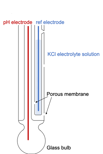
A standard glass electrode comprises of a glass bulb which is specifically designed to be selective to hydrogen-ion concentration. The glass bulb is up to 0.4 mm in thickness for durability and has silicate functionality on its surface, which provides binding sites for alkali-metal ions and hydrogen ions from the solutions. Once the bulb is placed in the test solution hydrogen ions in the test solution exchange for other positively charged ions on the glass bulb, creating an electrochemical potential across the bulb.
The reference electrode is insensitive to the pH of the solution, being composed of a metallic conductor, with a silver/silver chloride layer, which is immersed in an electrolyte solution, typically potassium chloride. The reference electrode comes into contact with the test solution through one or more porous ceramic membranes.
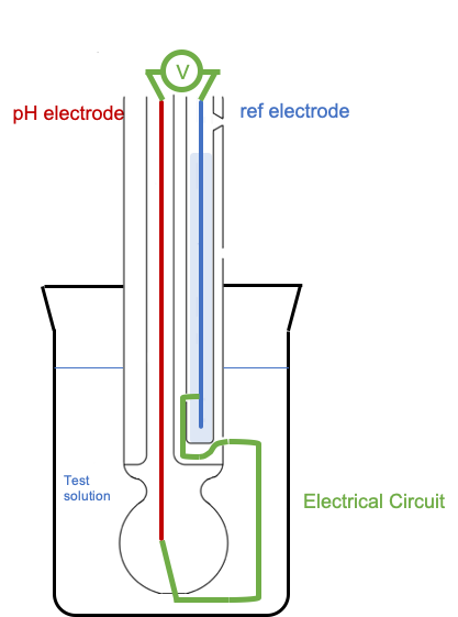 When the glass electrode and the reference electrode are placed in the test solution, an electrical circuit is completed, in which there is a potential difference created, amplified and detected by the voltmeter.
When the hydrogen ions in the test solution equilibrate with the ions on the surface of the glass bulb a stable potential difference is created outputting a particular millivolt signal. This millivolt signal corresponds to a pH value. The magnitude of the electrochemical potential across the glass bulb is linearly related to the pH according to the Nernst equation, so for a standard combination pH sensor an output of 0mV is equal to pH 7 at 25C and this changes by +/- 59mV per pH unit.
The theory behind calibration
This is great in theory, but in practise and over time, this millivolt signal drifts further away from where it should be. This results in a change of Slope or a millivolt offset, or Asymmetry Potential.

Most of the causes of millivolt offset are down to the reference electrode. Depletion of the KCl electrolyte from the reference electrode chamber, or poison of this electrolyte from the test solution will all lead to drift in the reference electrode potential, and so to erroneous millivolt signals. To overcome this, glass pH electrodes need to be frequently calibrated.
The general process for calibration is to use at least two buffer solutions with known pH values – typically pH 7.00 and one or both of pH 4.01 and 10.00. The subsequent mV outputs are then adjusted, and the sensor is good to go again. Over time, or in particularly nasty test solutions, when the slope (or efficiency) and the millivolt offset becomes too large, the probe has to be replaced.
Reducing the frequency of calibrations
It has long been a dream of pH sensor manufacturers and end-users to find a way of avoiding reference electrode drift. Over the years companies have tried to overcome this reference electrode drift by making improvements to various parts of the sensor. Double junction probes, like the ones depicted above, have two junctions to get through to the test solution. This helps to maintain stability of the reference electrode and delay poisoning of the electrolyte. Algorithms are also used to try to predict the reference electrode drift. This is helpful in a process environment where the test solutions and conditions are always the same and so the drift can be predicted more reliably.
 ANB Sensors have developed a novel technology looking at a solution to this problem from a completely new angle. We’ve seen ways to delay reference electrode drift, or in some cases predicting it, but we know it can’t be stopped entirely as it is intrinsic to the sensor. So instead, we’ve come up with a novel way to track the drift, thereby allowing the sensor to self-calibrate.
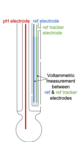
It works by placing a second electrode into the reference chamber, alongside the reference electrode. This reference tracking electrode periodically measures for any drift in the reference electrode and then automatically compensates for this in the pH measurement. It can be retrofitted into any existing glass electrode and negates any need for manual calibration.
What are the advantages of not having to calibrate?
Without having to manually calibrate, many more sensors can be deployed and entire water networks can be monitored. This is of particular relevance with the increase in regulations. As the accuracy of the measurement over time is no longer an issue, the sensors can be meaningfully networked into the IoT with complete confidence in the pH readings gathered. There will be no down time of the sensor – the erroneous measurements taken when the sensor has lost accuracy and is waiting to be recalibrated will be a thing of the past. Along with the labour cost saving for the engineer who currently goes out to calibrate the sensors, there is also the environmental impact of travel, logistics and calibration standards that will be avoided.